31 Results
View results:
Sort by:

When it comes to wind loads on building type structures as per ASCE 7, numerous resources can be found to supplement design standards and aid engineers with this lateral load application. However, engineers may find it more difficult to find similar resources for wind loading on non-building type structures. This article will examine the steps to calculate and apply wind loads as per ASCE 7-22 on a circular reinforced concrete tank with a dome roof.

Windbreak structures are special types of fabric structures which protect the environment from harmful chemical particles, abate wind erosion, and help to maintain valuable sources. RFEM and RWIND are used for wind-structure analysis as one-way fluid-structure interaction (FSI).
This article demonstrates how to structural design windbreak structures using RFEM and RWIND.
RWIND 2 is a program for generating wind loads based on CFD (Computational Fluid Dynamics). The wind flow numerical simulation is generated around any building, including irregular or unique geometry types, to determine the wind loads on surfaces and members. RWIND 2 can be integrated with RFEM/RSTAB for the structural analysis and design or as a stand-alone application.

With the release of the structural analysis programs RFEM 6, RSTAB 9, RSECTION 1, and RWIND 2, Dlubal Software introduces a new generation of structural analysis programs. True to the motto "Structural analysis that is fun ...", the program provides users with universal tools with which they can meet all the requirements in structural engineering. Find out more about the latest developments at Dlubal Software in this article.

RFEM 6 includes the Form-Finding add-on to determine the equilibrium shapes of surface models subjected to tension and members subjected to axial forces. Activate this add-on in the model's Base Data and use it to find the geometric position in which the prestress of lightweight structures is in equilibrium with the existing boundary conditions.

By means of result combinations, it is possible to create, among other things, the envelopes for internal forces and deformations. Thus, you can quickly find the maxima and minima for the subsequent design.

For designing glass in the RF‑GLASS add‑on module, you can use one of two calculation methods: a 2D or a 3D calculation. The main difference between these design options is the automatic modeling of the layers in a temporary model. In a 2D calculation, each layer is generated as a surface element (plate theory); in a 3D calculation, it is generated as a solid. Depending on the selected layer composition, you can either select an option or find it preselected by the program.
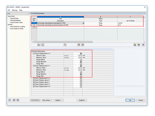
To control the lateral displacements of a model, you can use the RF-/LIMITS add‑on module. This add‑on module allows you to, for example, run a serviceability limit state analysis to find horizontal nodal deformations and to set it against a limit value.
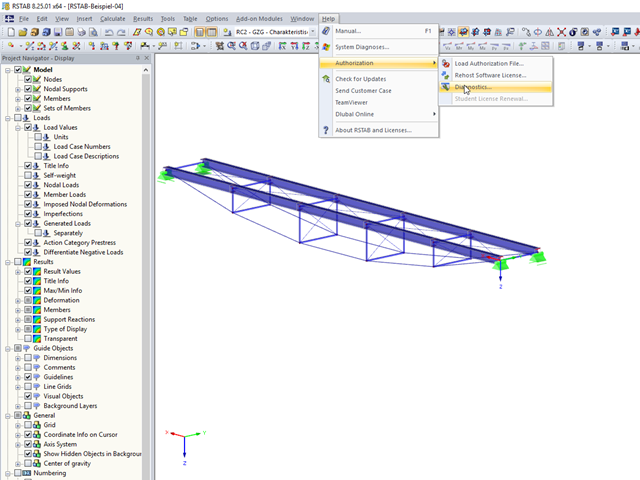
In RFEM 5 and RSTAB 8, you can view detailed information on the currently used license and installed dongle driver. In case of any problems with the license, you can send the created text file to the Dlubal Software hotline, which allows us to provide you with a fast and efficient analysis. To create the file, select "Help" → "Authorization" → "Diagnostics".
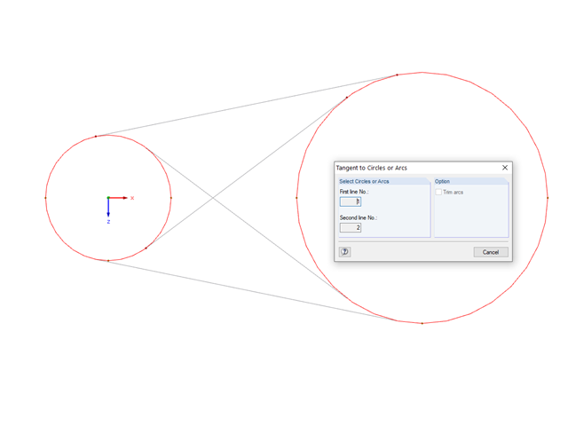
The "Tangent to Circles or Arcs" function can make modeling easier for you. You can find the appropriate command in the "Tools" menu.
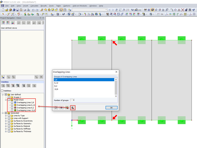
When modeling in RFEM, double lines may be created. To quickly find and delete them, if necessary, RFEM 5 allows you to export overlapping lines. This is possible, for example, in Excel or in a separate group of sections.
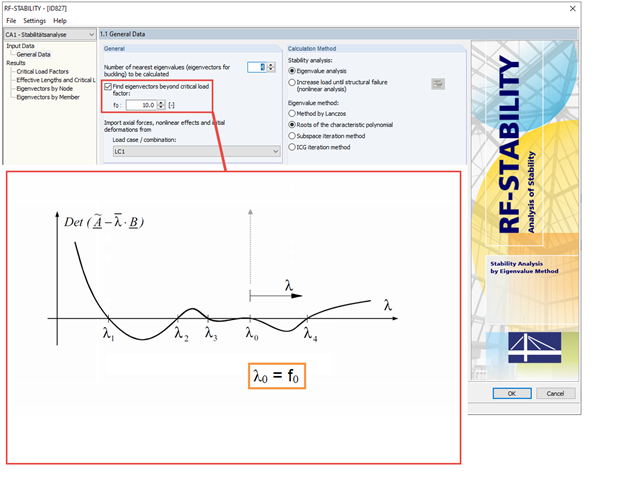
The function, which is also known as shifting, allows you to calculate critical load factors beyond a user‑defined initial value. Determination of the critical load factors is usually done from the smallest to the greatest critical load factor.
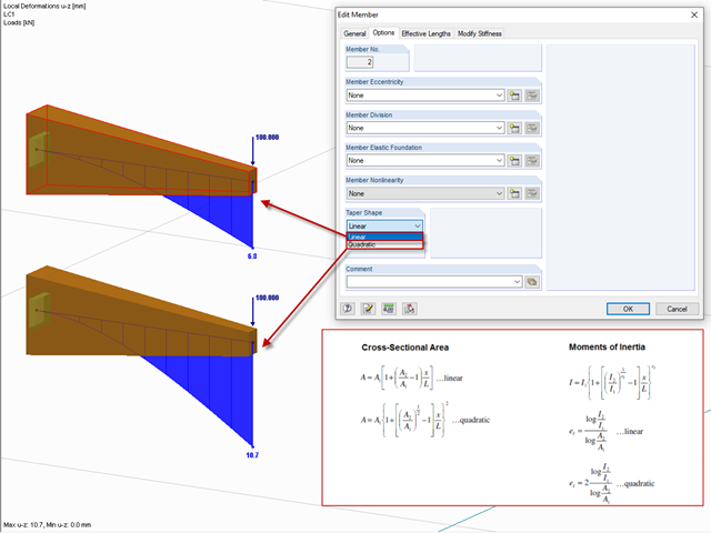
After right-clicking a member and selecting "Edit Member", you can find the "Taper Shape" option in the "Options" tab.
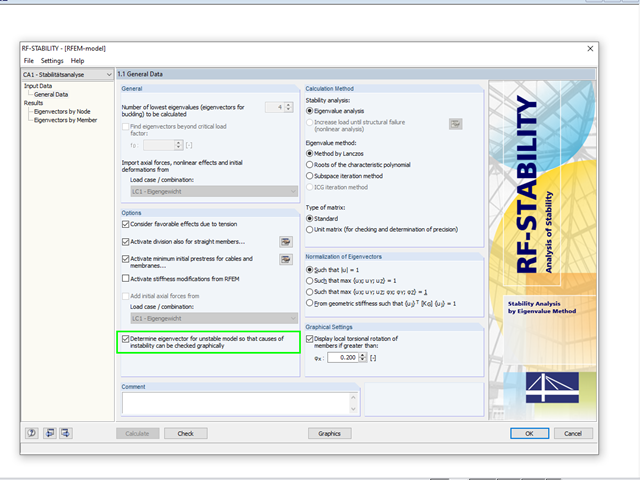
A calculation break‑off due to an unstable system can have different reasons. On one hand, it can indicate a "real" instability due to overloading of the system; on the other hand, the error message can result from inaccuracies in the model.
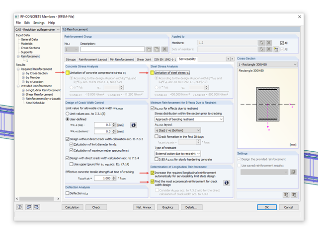
In Part 1, the selection of the design criteria for dimensioning the reinforcement for the serviceability limit state design in RF‑CONCRETE Members and CONCRETE was explained. Now, we go into detail for the function "Find economical reinforcement for crack width design".

When it comes to wind loads on building type structures as per ASCE 7, numerous resources can be found to supplement design standards and aid engineers with this lateral load application. However, engineers may find it more difficult to find similar resources for wind loading on non-building type structures. This article will examine the steps to calculate and apply wind loads as per ASCE 7-16 on a circular reinforced concrete tank with a dome roof.
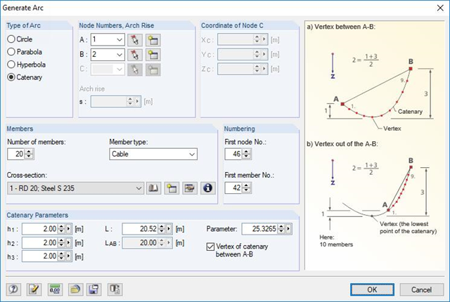
RFEM and RSTAB are able to cover a large number of branches in the building and construction industry with their generally usable structural frame analysis and FEM programs. Designing cable structures is thus also possible in both software solutions. Some assistance tools for modeling and design will be presented in the following text.
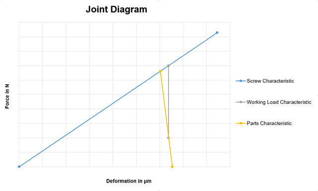
When modeling surface models, such as a frame joint or similar structures, there is always the question of how to model a prestressed bolt connection. In this case, it is always necessary to find a compromise between the practicable and detailed solution. The following article describes the modeling procedure of such a connection, based on the joint diagram calculation method.
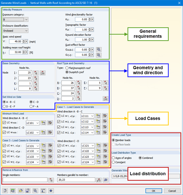
RFEM and RSTAB allow you easily to consider wind load effects on a three-dimensional building according to ASCE/SEI 7‑16. This article explains the complex theory of entering wind loads in the software. You can find the wind load under "Tools" → "Generate Loads" → "From Wind Loads".

Cable and tensile membrane structures are regarded as very slender and aesthetic building structures. The partly very complex double-curved shapes can be found using suitable form-finding algorithms. One possible solution is to search for the form via the equilibrium between the surface stress (provided prestress and an additional load such as self-weight, pressure, and so on) and the given boundary conditions.
![Basic Shapes of Membrane Structures [1]](/en/webimage/009595/2419502/01-en-png-png.png?mw=640&hash=5e657e3feb5c1bb6d21727468dd85d91e1c9f29f)

With RFEM 5.06 and RSTAB 8.06, the examples and help files for programming the COM interface are not only available on the Internet, they are also included in the installation. To find them, look for the "SDK" folder in the project directory (usually C:\Users\Public\Documents\Dlubal).
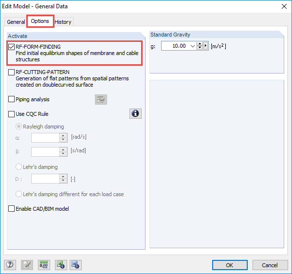
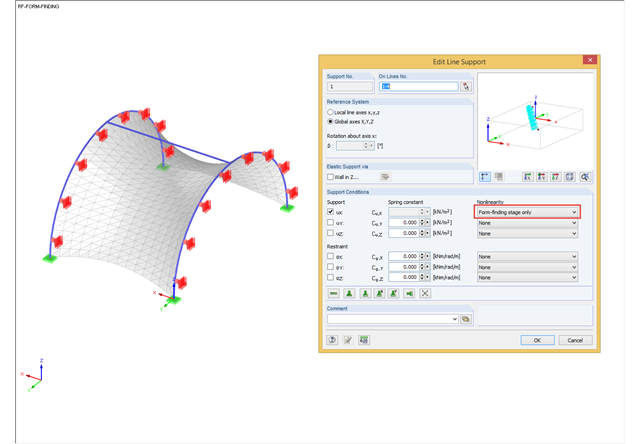
The RF-FORM-FINDING add-on module determines equilibrium shapes of membrane and cable elements in RFEM. In this calculation process, the program searches for such geometric position where the surface stress/prestress of membranes and cables is in equilibrium with natural and geometric boundary conditions. This process is called form-finding (hereinafter referred to as FF). The FF calculation can be activated in RFEM globally in the "General Data" of a model, "Options" tab. After selecting the corresponding option, a new load case or a calculation process called RF-FORM-FINDING is created in RFEM. An additional FF parameter is available for defining surface stress and prestress when entering cables and membranes. By activating the FF option, the program always starts the form-finding process before the pure structural calculation of internal forces, deformation, eigenvalues, etc., and generates a corresponding prestressed model for further analysis.

The form-finding process in RF-FORM-FINDING displaces the corner nodes of FE elements of a membrane surface in space until the defined surface stress is in equilibrium with the boundary conditions. This displacement is independent of the element geometry. In the case of elements with four corner nodes, the free displacement may cause spatial drilling in the element plane and thus exceed the validity limits of the calculation; therefore, triangular elements are generally recommended for form‑finding systems. Triangular elements remain independent of the corner node displacement and stay within the calculation limitations.
During the form-finding process, the slip modulus of a substructure is also taken into account when searching for the equilibrium state. You can also consider large deflections of supporting trusses or pure bending deformation of the edge beams when determining the membrane shape.
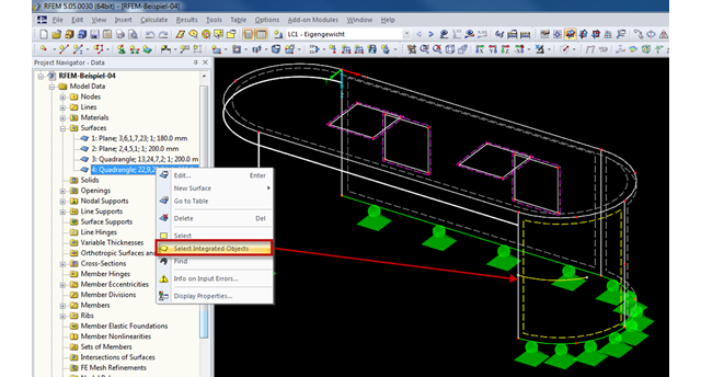
Generally, RFEM automatically detects all objects lying on a surface that are not used for surface definition. Objects integrated into surfaces can be selected using the "Select Integrated Objects" option in the shortcut menu of the relevant surface in Project Navigator. This way, you can easily find in the graphics which objects have already been integrated into a surface, for example.
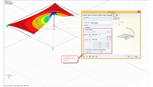
The form-finding process in RFEM seeks an equilibrium state where the defined prestress of membranes and the prestress or length changes of cable elements with boundary reactions are in equilibrium. For this, the program provides the option to define an isotropic or an orthotropic prestress state for membranes.
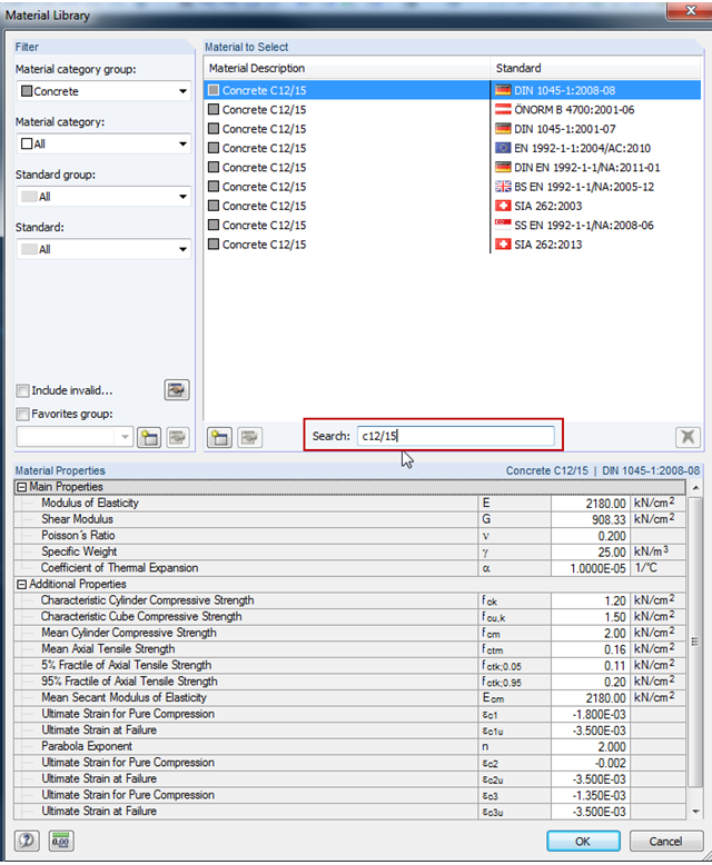
RFEM and RSTAB include an extensive materials library, which can be extended by user‑defined materials. Starting with version X.05, the materials library provides a convenient full‑text search. This way, you can find materials more quickly.
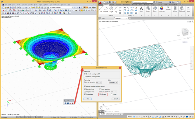
In RFEM, there are a file‑based and a direct DXF interface. The file-based DXF interface allows you to export the data in a DXF file that is transferred directly into an open AutoCAD file. In the interface dialog box, you can select which data are to be exported (results as isolines, result values, or finite element mesh with boundary and integration lines).
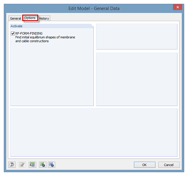
The RF‑FORM‑FINDING add‑on module can be activated in the "Edit Model - General Data" window, "Options" tab. By activating the module, a new RF‑FORM‑FINDING load case is created and an additional menu appears in the main program, allowing for the definition of prestress conditions for membrane and cable elements.